I’ve made good progress on the battery regulator stacks. Both are assembled and the 8-stack for the rear pack is installed in a casing. I still want to add the fans but first I’ll probably run the wiring and figure out the mounting in the car. It will go next to the charger.
First up though is removing the charger and trimming the carpet up in the rear hatch. The finished product will have the charger installed on top of the stock carpeting, which will tuck under the access hatch for the rear 8 batteries.
On a side note, my wife’s Acura battery is dying again after 2 years. I’m tempted to get a Diehard and be done with it but with prorated warranty they encourage 2-years batteries with a 100k mile warranty…
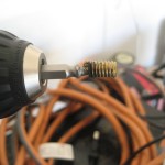
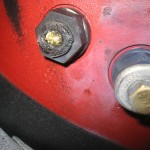
I borrowed neighbor Mike’s 90 degree drill and was able to get the melted bolt out without too much trouble. The threads showed no sign of damage outside a little of the melted black plastic that stuck to it so I think I escaped with only a bolt replacement.
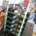
I also took a picture of the new battery regulator rack I’ve been working on. I need a bunch more spacers from Ace but I think it will work out well. My plan is to mount them inside a steel box I’ll make out of sheet metal and install some fans that will be powered by the external load jumpers on the regs.
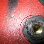
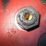
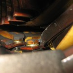
Here are some more pictures of the melted bolt. It’s motor terminal S2. I removed the motor shroud from the forced air cooling so I could see from the inside what the bolt attaches to. I can’t get at the bolt with a bolt extractor without pulling the transmission and removing the motor mounts to rotate the motor so I wondered if I could unbolt the outer “nut” that the bolt goes into. It almost looks like a coupler that the wires from inside the motor connect to as well. My guess is that as long as I can get the inside to bolt back in I should be able to remove the coupler, extract the bolt on a work bench, then reinstall.
I will probably call the manufacturer first though. It does look like some ash/dust has spread into the motor so I don’t know if I need to take off the front motor cover and clean that up or not.
On a side note, I’m hopeful that the bolt melted on the first test run and every drive since then has been lacking power due to the small contact area holding the motor terminals together. It was so minimal when I tried to rotate the cable to see if it would turn the bolt the cable came free very easily so there wasn’t much contact.
Also decided to take everything apart and reinstall having knowledge of how it should go. This time around will be cleaner and safer (no exposed wires carrying full pack voltage within hand’s reach). So today I removed all battery regulators, battery cables, controller and board. It’s basically down to motor and batteries.
Tags: damage, motor Posted in doing | Comments Off on Back to that Bolt
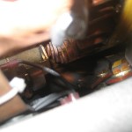
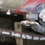
Tonight I was looking under the hood just to check stuff out and came across this. This is my S2 motor terminal and the 2/0 lug that was bolted to it. I imagine it got loose and welded itself into this mess.
I’ll have to see if it will unscrew or not and figure out how to get it back together.
I removed the scooter motor and the power steering pump to eliminate some weight and clean up the engine bay. I was going to remove the A/C compressor and the entire front bracket since I need to figure out a way to get that to work. Problem is we welded the bracket to hold the bracket that holds the A/C in place and the gaps between the frame and the welded piece are smaller than the parts that need to come out.
So I think I can get to it by removing the sway bar and coming out the bottom but I’ll need to lift the car back up to do that.
One oddityI found was that disconnecting the negative most battery cable did not reduce the voltage between the contactors to zero as I’d expect. Until I disconnected the battery regulator lead it didn’t drop, so i assume there are capacitors on the regulators which hold charge so you could still get a slight zap from those.
It’s getting cold here in Florida so I may bump up the heater replacement.
Since I’ve been driving Trans Amped it has been more difficult to work on it. With it formally up on ramps and jackstands it was no problem to crawl under and do stuff. Now I basically have to setup before working and I don’t like doing that.
So I haven’t done anything in a while but up next is removing the power steering pump and A/C and associated brackets. That will probably be about 50 lbs out of the front end and will allow much more flexibility in my control board layout. I’ve got an idea of making an enclosure where wires go in, wires go out and everything else is hidden. Now that the car is moving and people are seeing it I’m going to be more careful about making the ability to tap into the full pack voltage, currently about a foot apart, a little more difficult.
Also on the agenda:
Figure out a heater to use before it gets cold.
Change the battery regulators wiring to 10 guage and relocate the regulators off battery
Rear battery cover and carpet modification
Relocate front battery regulators to a drier spot
Fix the manual steering rack. The alignment shop said it wasn’t centered and they can’t align it because the tie rod is all the way in already and the toe is still out.
Granted, all it did all day was sit there, but it did at least go.
After last night’s unadventurous drive to dinner I opted to fill ‘er back up and make the slightly longer trip to work, about 15 miles round trip. I took the back roads to keep it under 45 since I was engaged in traffic.
Went 15 miles, voltage when complete was 154. Starting was 168 so it did pretty good as far as range. Charging back up now. It’s been about 3.5 hours at 13.5 amps so we’ll see where it is.
Tags: batteries, drive Posted in Blog | Comments Off on Trans Amped goes to work
Tonight we went out to a pizzeria that is 5.8 Google miles away. The pack wasn’t quite topped off from a quick lap around the neighborhood the other night so we started at 166 V. Finished voltage was 155.3 so we used 11V to go 11.6 miles, about a volt per mile which is easy to remember. I don’t understand why everyone says 300 watts per mile, I suppose because pack voltages vary.
So instead of saying I need 300 watts of power to go 1 mile, to me it makes more sense to say I’ll consume 1 Volt to go one mile. Voltage is potential so I like the idea of saying I’ve got 30 volts to use at 20% discharge so at 1 V/mi I can go 30 miles. Less as the pack is depleted, but about that.
Besides, who has a meter for watts installed in the car to tell them how much fuel is left, seems everyone uses a voltmeter for “fuel” and an ammeter for instantaneous use.
So after the clunk videos we opted to be brave and took Trans Amped to dinner at Route 46, about 2 miles away with backroads we could take.
For those without a Trans Am, when the weather looks like this you take the t-tops out and go cruising. Just like the good old days but all electric.
Now I’ll get technical. We figure we went about 4 miles. The batteries weren’t fully charged because of the earlier testing in the neighborhood (I did that about an hour before dinner) so the pack voltage was about 172 while charging, so probably 168 resting. After the 4 miles the measured voltage was 162. so if we used say 8 volts to go 4 miles I can take the pack down to 125 (80% of 156) that means I have about 45 volts worth of safe go juice. At roughly 2V per mile that means I’d be able to go 22.5 miles. I’d expect the mileage to decrease along with the pack voltage though so probably a little less. Yay onboard charger! This is the lowest the pack has been so I’m interested to see how long it takes at 13.5 to recharge. I need to get that 220 line installed. I do have an anniversary coming up soon…
Keep in mind the speedometer and other gauges don’t work (only the ammeter) so I’m guessing at the distances and even the volts. But it’s inline with what I’d expect. Speeds were probably 25-40 mph which is typical for my driving, maybe closer to 45 though. Amp draw in 4th at ~35 mph was a pretty stead 75 to 100. Pushing the pedal a bit more and the amp draw would increase to 800 at the highest I saw. Still haven’t tried full throttle, I’m enjoying it working after a year and a half of build and don’t want to break something just yet.
Tags: batteries, drive Posted in Blog | Comments Off on Trans Amped took us to dinner
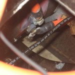
Here is a video I shot today. Troubleshooting the rear end clunk has me confused and since it only happens when you are driving and I am the driver I figured I’d tape the camera under the car and then drive. Out of 4 minutes here is 14 seconds. Second 10 is the interesting one. I’ll sort through the rest and decide it any more is worth posting. It’s a pretty cool video just to see the driveshaft spinning. It goes pretty dang fast for being under 20 mph most of the time.
For viewing understanding: The video is rotated 90 degrees. The ground is to the left and the inside of the rear driver’s side tire is on the top of the screen. The camera is mounted to the passenger side lower shock bolt looking at the rear pumpkin with the torque arm behind the driveshaft. Hope that clarifies.
Posted in Blog | Comments Off on Driveline Video!!!