Archive for the ‘doing’ Category

Power Steering Motor

Monday, June 15th, 2009

Yesterday I put together the wiring for the power steering motor while watching the Nascar race. I’ll have to put up some pictures later, but I think it came together pretty well. I used heatshrink and all so its very professional looking. The only wire I need to figure out is the trigger to the relay. I want it to be on when the key is turned to on, same as the main contactor so I think I’ll just tap into that.

I’m wondering though if I want everything to be triggered off the same line from the fuse box. If something went out with that connection the Trans Am would become a glider with no power steering and only the vacuum remaining in the reservoir for brakes. It should be sufficient for a stop or two at least. The benefit would be if everything is triggered off the same line, a single LED in the dash would tell me whether it is all working or not. I think I’ll do that. The contactor already has auxilliary wires to indicate when it is open (light off) or closed (light on).

Power Steering Motor

Monday, May 11th, 2009

I figured out the wiring for the motor that will drive the power steering pump. I wanted a way to shut the motor off when PS wasn’t needed to save some amps. This would be primarily when sitting at long traffic lights, but I could also see using it on the interstate occasionally. I really depends on the amps the motor ends up drawing and if the PS pump can be cycled on and off. If it takes 5 seconds after switching the motor on for the lines to be pressurized then it’s a no-go.

My original thought was to tie into the parking brake light indicator. This comes on when the parking brake handle is engaged even a single click. There is continuity in that wire that I was going to use to trigger my relay. Turns out though I would need a normally closed relay and then the brake was engaged it would open the relay. That’s not what I bought, so considering that and the fact that the brake light is on all the time currently (when a battery is connected to the frame for testing) I opted to instead use a switch the presious owner had installed for some fancy blue light special around the radio bezel.

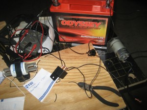
Here is me figuring out how everything needs to be wired with a junk motor from a cordless grass trimmer. The switch triggers the relay which can handle the amps of the motor. The switch even has a little light on it when it is on.

12V, 1200 amp battery makes 18V tiny weed wacker motor whirrrrrr!

12V, 1200 amp battery makes 18V tiny weedwacker motor whirrrrrr!

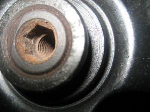
The next step is to figure out how to mate the shaft of the motor to these threads or hex (9mm?) opening on the PS pulley. And also how to mount the motor itself to maintain a parallel connection between the two. I think I’ll sleep on it some more.

The motor mount reveal

Monday, May 11th, 2009

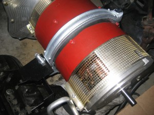
I realized I never posted any pictures of the motor mounts, so here is one:

The silver ring is actually meant for petroleum pipe lines, 10″ to 12″ diameter. I purchased it from JM Ellsworth. I see irony in that. Shipping was fast and I think it worked out well. The thickness of the band is just larger than the spacing between the bolts around the motor so I had to grind a little material off one side, otherwise it went in pretty easy.

Over the motor boards

Monday, May 11th, 2009

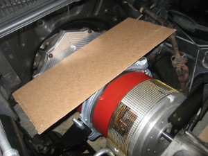
I started to layout the front batteries now that I’ve decided to go bigger. A simple math correction revealed that 156 / 12 = 13, not 14, as I’d previously thought. So I only need to cram 13 batteries in the car, meaning 8 out back and 5 under hood.

Three batteries end to end along here

Three batteries end to end along here

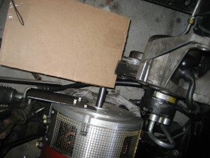
Two batteries side by side here - need to clear the accesory bracket and front shaft.  Speed sensor will be there.

Two batteries side by side here - need to clear the accesory bracket and front shaft. Speed sensor will be there.

This is the room I have left for the controller, DC-DC and fuses, contactor, etc.

This is the room I have left for the controller, DC-DC and fuses, contactor, etc.

Battery Cables

Saturday, April 25th, 2009

Check it out, we made a custom battery cable today.
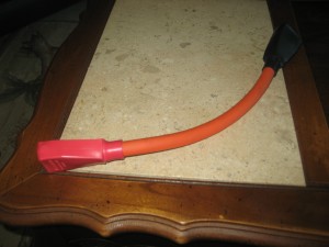
12 incher, a bit longer than needed

12 incher, a bit longer than needed

I got my new shipment of battery terminals on Thursday. I mailed the parts back for exchange on Saturday, all the way to Utah. I’m very happy with the service I’ve received from EVSource. After today’s experience, I think I’ll need to place another order with them to take advantage of their tool rental program. Here’s the scoop:

I’d just come home with a pair of high-leverage Klein cable cutters from Home Depot. I stopped at Sears a few times to get a pair and their cable cutting selection was mostly cleared out, so I was happy to find them at Home Depot, meant I didn’t have to mail-order and wait.

Anyhow, I figured I had my new terminals, terminal covers, wire (seems to be called “cable” once it’s 2/0 size so I better start to if I want to seem like I’m professional-like), heatshrink and cable cutters. Might as well make a battery cable, right? I thought so.

I pulled up the specs on my batteries, some paper and some theory a guy name Pythagoras figured up. Take the distance between the terminals squared plus the width of the battery squared and then desquared and I got about 10.85″. I added a smidge for a buffer and measured roughly 12″ out of my 20′ coil of wire.

Back out came my Klein high-leveraged 9″ cable cutters. I found my mark and clamped on. About 15 seconds of claming later I figured I needed to figure something else out since I couldn’t seem to leverage enough on my high-leveragers. I pulled out some 1′ socket extensons and deep sockets that fit snug on the handles and gave that contraption a squeeze, but to no avail.

I then thought to put the handle between the gap on my Craftsman clamping professional work table. That did the trick pretty easy – basically like putting the handles inside a vise. So now I had a cut to length cable. Used the cable cutters to slice through the outer sheath of the cable and pulled it off.

Assembled it all together so we had the terminal covers on, then the heat shrink, then the terminals. Then I realized I had the black terminal cover on the side with the positive terminal. Good thing it wasn’t crimped yet – you need to QC these things.

I’d previously found a boat store locally that provides a benchmounted crimper for making battery terminals. So we loaded into the gasmobile and drove on up there. Once there I took a good look at the crimper and realized it wasn’t quite big enough for 2/0. Figured I give it a whirl anyways.

It closed down pretty easy – I’d even say it was high-leveraged. We took a look at the terminal and it actually went through the lug and exposed the copper cable a tiny bit. We went ahead and did the other side too being careful not to cut through. I’ll keep a close eye on the terminal and make sure it doesn’t get hotter than the others indicating the connection isn’t very good.

We headed to the battery store after that to see how Pythagoras did with that math. We set 2 batteries wide to side like they’ll be in Trans Amped and the battery was about 4″ longer than it needs to be… That’s more than a smidge so I blame Pythagoras. Lesson learned so I made a note of how long the next cables should be.

Got home, fired up my new heat gun (located in the paint section, not heat shrink section of our neighborhood Ace) and shrunk the wrap around the crimps. All done.
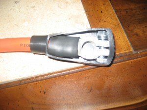
I haven't had many pictures lately, so here is another.

I haven't had many pictures lately, so here is another.

Overall it should go pretty well since I figured out the kinks. The only other thing was the terminal covers fit snug on the cable, so when the heat shrink is added it gets mighty tight, Barn. Sorry, we’re watching Andy Griffith right now.

Also bought some misc. wiring and connecters for my low voltage system.
Small things

Monday, April 20th, 2009

I ordered the wrong size lugs so I sent them back for smaller ones.  The screws for the batteries measures just over 5/16″ so I thought I needed to order the next size up – 3/8″.  Turns out the lugs, at least the ones I got, are oversized so they were 0.05″ too big.  The connections was a little sloppy so I’m going with the smaller size.

It works out well, because with the battery swap I’m going to need to use the SAE posts on top of the battery.  The new battery has both SAE terminals on top and screw post on the side.  If I want to put the batteries in rows front to back, the screws posts would not be accessible for the cable.

I also found a leak with the vacuum pump.  When I put the muffler on the o-ring slipped to the side and wasn’t sealing right.  While I had the reservior and pump off I added a pad beneath and to the side of the pump to keep it a little quieter.

Other progress was painting and bolting up the motor mounts.  I need 2 bushings and 2 more bolts and they’ll be done.  I should take some more pictures.

Motor Mounts

Tuesday, April 14th, 2009

We made some motor mounts over the weekend.  Thanks to a friend who helped me weld them together and even let me try a piece.  So I’ve now welded a total of about 4 inches!

I was surprised when I got home that after all the trial fittings I’d done, I ended up welding the mount together backwards.  I was even more surprised that when I went ahead and installed it backwards, it worked anyway.  That’s good design work from what I hear.

I’ve got a couple more holes to drill in the metal before it’s completed.  I’ve gotten lax about carrying the camera our to the garage everytime I do something but I’ll have to pull the mounts out probably one more time and will take a few pictures then.

Also of note, the right tools certainly help.  I needed 3/8″ and 1/2″ holes drilled into 1/8″ steel and the biggest drill bit I had was 1/4″.  So I drilled away and then used a punch to open it up a little more.  It took a long time and many whacks of the hammer.  Fortunately, for the 1/2″ hole I remembered my better set of drill bits that went up to 3/8″.  So I used those.  Then I used a jigsaw to run slots from the hole outward, expecting it to make the punching easier, but it didn’t.  So I bought a file tonight and worked at it for about 10 minutes until it was the right size.

Also, even if your drill only goes to 3/8″, they make 1/2″ and larger bits that have a reduced part to fit 3/8″ drive drills….  That would have worked too.

Small progress

Tuesday, March 24th, 2009

Not much change on the actual car, but I have been up to some stuff:

  • Made wood mockups of motor mounts and then sketched them up. I’ll remake them and assembly from the sketches to see if it still makes sense.
  • Thought a lot about the power steering and A/C pulley system.  They rotate opposite directions so it’s a little more involved than hoping.
  • Realized the placement of the battery terminals means that a cable won’t fit between the batteries unless I purposely use an odd battery arrangement.  I have an idea on solving that…
  • Got a new shipment of parts – battery lugs, plastic terminal covers, contactor, circuit breaker, fuse and holder
  • Found the oversized 40 amp fuse at a boat store
  • Found out the boat store has a cable crimper to make battery cables that customers are allowed to use, preferably if you bought your stuff there but they were pretty nice…

More later.

Vacuum Pump

Saturday, March 14th, 2009

The vacuum pump was purchased as a kit from EV Source.com with the reservior. The reservior is actually from Summit Racing, but it is about the same price from either source.

I do recommend reading the installation instructions from both EV Source and Summit prior to doing anything.

Thoughts:

Mount the reservior close to the vacuum pump.
Locate mounting surface for the pump, which must remain vertical so the oil doesn’t leak.
If you drill holes to mount anything, be sure you have access to the backside to place and hold bolt or screw.
While laying out the hose plumbing, keep in mind the wiring has to connect to certain places as well (positive battery, live wire to activate relay, frame ground).
Don’t install the reservior before you remove your light.
I think that the relay activation wire should tap into a line that is live with the key in the on position.

More later…

Vacuum Pump Install

Saturday, March 14th, 2009

Today I installed the vacuum pump for the braking system. I ordered a kit to make it easy and am very impressed by it’s contents. I think the instructions could be a little more clear but overall it’s a good package.

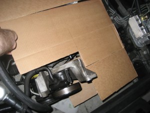
I chose to mount the pump in the vacancy left by the air filter box. This places it on the driver’s side, right in front of the ABS unit and the power brake booster. There was already an opening in the frame I could put the pump’s mount through, and also a hole adjacent that I used to bolt it down. I’m very happy to reuse existing holes and not cut up the Trans Am too much.

Mounting the reservior was a little more difficult. In that location there aren’t many flat surfaces large enough for the tank to reside. One location that looked promises was ruled out because of possible clearance issues once the hood is reinstalled. I ended up using that spot, but rotating the reservior by 90 degrees. This actually worked out better because the hose connections are able to point in the right direction without much hose bending.

I’m still thinking about the wiring. I need to access the positive battery which is on the other side of the car, but the cable connected to the motor isn’t long enough. If I keep the fuse and relay assembly under the reservior, I’ll need to add about 4 ft to the wiring harness for that connection. If I put the fuse and relay assembly near the battery, I’ll need to run 3 wires across the radiator support instead of only 1.

Here are some steps of the installation:

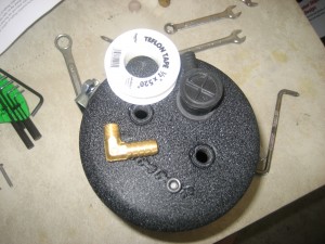
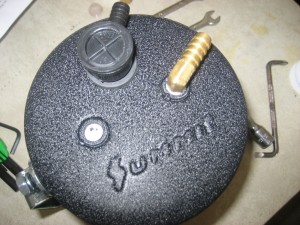
Reservior parts

Reservior parts

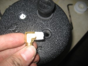
Summit says to wrap the threads in teflon tape to seal leaks.

Summit says to wrap the threads in teflon tape to seal leaks.

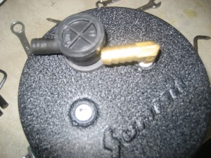
Summit includes instructions to install the check valve last so this doesn't happen, but I didn't get those.

Summit also says to install the check valve last so this doesn't happen, but I didn't know that.

The completed reservior.

The completed reservior.

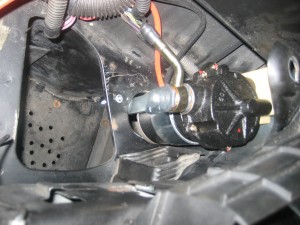
The vaccum pump installed.  The silver band rotates and slides up and down to mounting options.

The vaccum pump installed. The silver band rotates and slides up and down to mounting options.

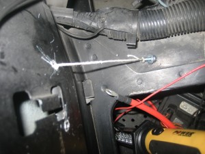
I used this trick to pull screws from a not very accessible backside to the mounting holes.

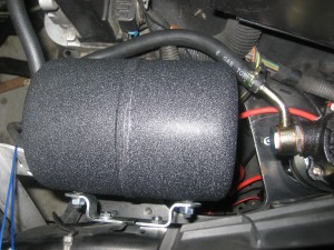
Reservior mounted on the bracket.  The pump is just to the right of it.

Reservior mounted on the bracket. The pump is just to the right of it.

These are the remaining parts of the plumbing between the reservior and the brake booster: check valve then pressure sensor.

These are the remaining parts of the plumbing between the reservior and the brake booster: check valve then pressure sensor.